Hunter Galvanizing wants you to consider the following when designing and fabricating ferrous articles for Hot Dip Galvanizing. There are a number of potential issues that must be taken into consideration prior to your steel item being galvanized, if these simple steps are followed, you are giving us the best possible practice to process the galvanized articles safely in return giving you a uniform protective coating.
Safety for Process
Safety is an important element of our work practices and there are a number of issues that we need our customers to be aware of to ensure the best possible outcomes. One of the most common and biggest concerns a galvanizer deals with on a daily basis is hole placement. Misplaced or non-existent holes can result in explosions during the galvanizing immersing process. This occurrence is a result of trapped air or pre-treatment liquid rapidly heating, creating super-heated steam. Due to this, Hunter Galvanizing will no longer accept any work that has been internally vented. If you insist that you want to internally vent your work, additional inspection holes near the internal holes will be required to allow our staff to accurately check your item. Overlapping surfaces which have been fully welded to another article is another example similar to no vent holes and needs to be considered when designing for Hot Dip Galvanizing.
Requirement for Holes
In order for items to progress through the series of pre-treatment and galvanizing baths at our facility; they must be suspended in a suitable manner to ensure all pre-treatment liquids and molten zinc can move freely in and out of all hollow sections and clean and galvanize all surfaces. If items are small enough, they can be outsourced and centrifuged in perforated baskets (spinning). This process is ideal for large numbers of nuts and bolts. Touch marks are often an issue with centrifuged items where they make contact whilst being processed.
In-house, some products are processed in specialised dipping frames or racks and allow large quantities of straight lengths to be galvanized at the same time. Minimal areas of the surface of each section will be in contact with parts of the dipping racks resulting in small touch marks, which, subject to quantity and end use of the items, may or may not be touched-up with zinc enriched epoxy paint.
Large assemblies are supported by chain slings or lifting fixtures. To enable safe handling, lifting points should be incorporated into the fabrication’s design, distributing the weight equally over four points. Lifting lugs and heavy-duty washers can be welded at the required points and then removed after galvanizing. These are preferable to chain or wire marks remaining after galvanizing. The coating can be repaired with zinc-enriched epoxy paint if aesthetics is an issue after removing unwanted lifting points.
Most general fabrications are suspended by wire on headframes and hung vertically or on an angle to maximise drainage of pre-treatment chemicals and molten zinc. Additional holes or lifting lugs may be required after fabrication to enable successful galvanizing of items.
It is important to understand the function of each hole for galvanizing before determining where to place them. The various functions of holes can be categorized into four requirements: hanging, prevention of pooling and entrapment, venting and draining, and to relieve pressure from overlapping surfaces.
High-end holes are air-exit points. Low-end holes are zinc-entry points.
Holes for hanging
The shape and dimensions of an item will determine how it is suspended during the hot-dip galvanizing process. Where possible, holes located in cleats, flanges or base plates will be used to suspend general fabricated items. If there are no holes available, they will be required to be added to enable the item to be hung in the correct plane, allow processing liquids to drain and to minimize distortion.
Hunter Galvanizing offers some general guidelines:
- Subject to weight, items less than 2m require a hole or lifting lug placed at one end. Longer and heavy items will require holes or lifting lugs at both ends. Holes should be a minimum of 10mm diameter, large enough for jigging wire to be passed through.
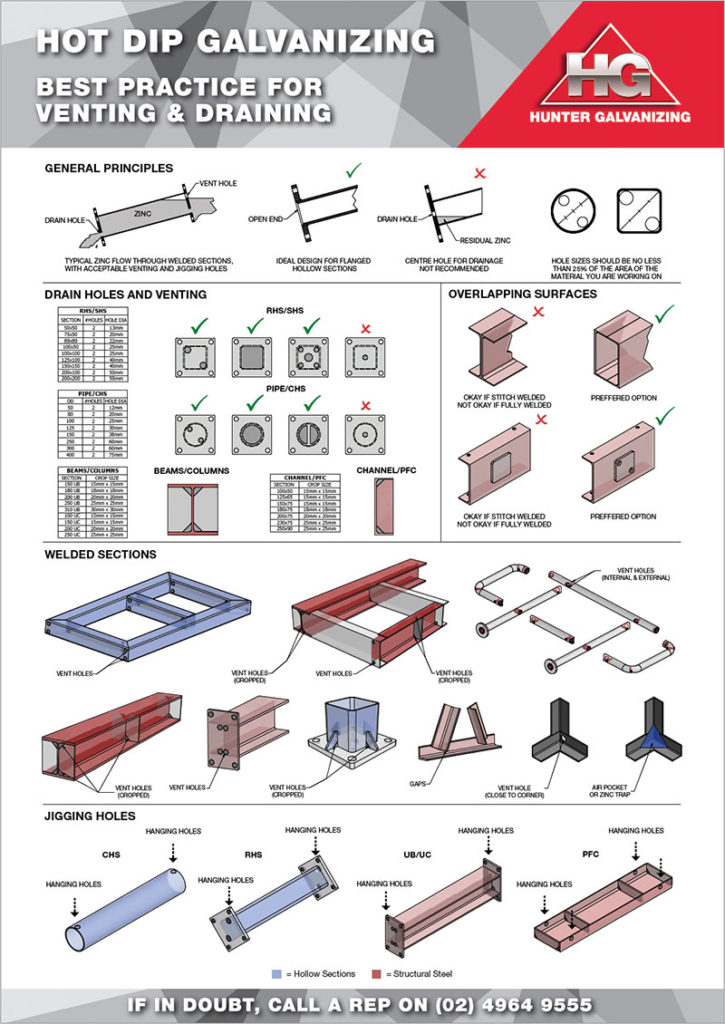
- Larger fabrications will require numerous wire strands to be used and hole sizes should be adjusted accordingly. Further information can be downloaded by clicking here, Best Practices for Venting and Draining, otherwise a Hunter Galvanizing staff member will be more than happy to discuss size and location of holes specific to each item.
Wire, chain or other touch marks
All items are processed in dipping frames, held by chains, or suspended by wire.
Small touch marks may be evident where the items have been in contact with the frame structure. Chains are used for heavy items and will leave touch marks in their immediate area as will wire if it is wrapped around an item or through hanging holes. The wire sticks to the surface of the galvanized coating as the item is withdrawn from the galvanizing bath. Touch marks or chain marks are usually completely galvanized, affecting only the outer free zinc layer of the coating and therefore not a reason for rejection.
Holes to prevent entrapment
When an item is suspended on a headframe, it remains in the same hanging position throughout the hot-dip galvanizing process. Holes are required to be in the appropriate location to ensure pre-treatment acids, molten zinc and zinc ash can flow freely from all surfaces as it is submerged and withdrawn from each processing bath.
General guidelines:
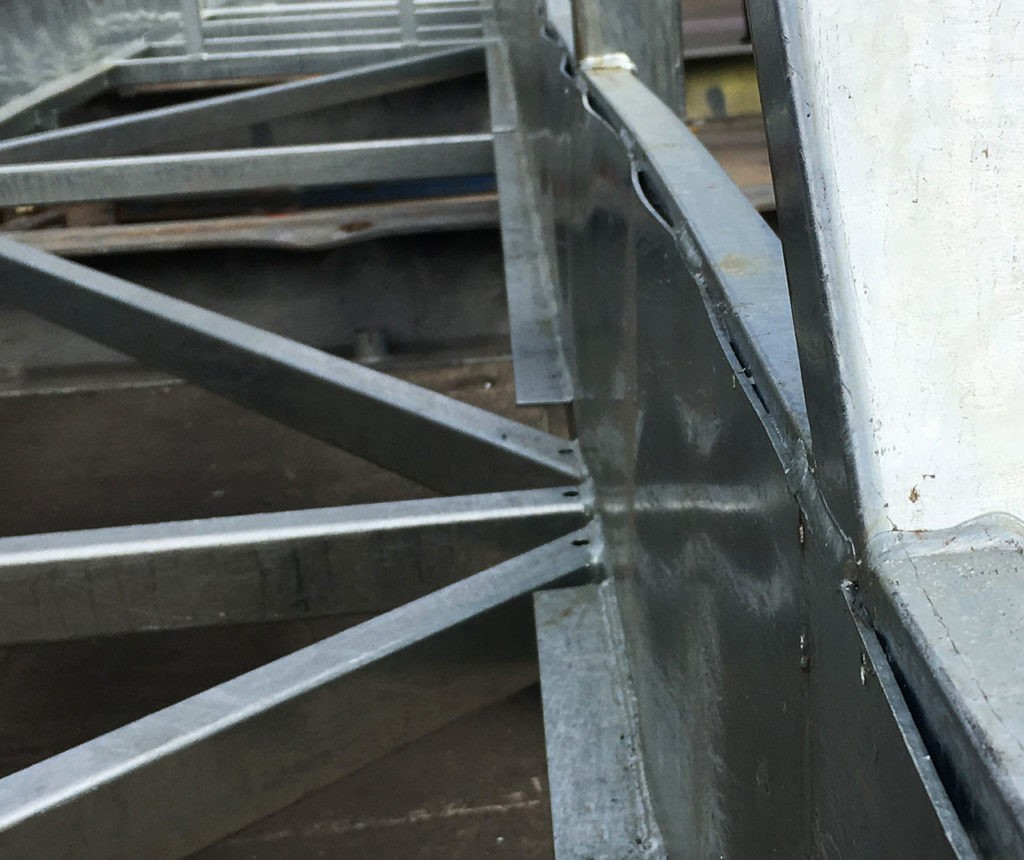
- A hole, gap or mitre in the corners of gussets or stiffeners will assist processing products to drain.
- Holes through end plates or web plates will also provide suitable access for zinc and zinc ash to drain and allow air to escape.
- By adopting a “hole in every corner” principle, the majority of issues relating to draining can be eliminated and the best possible hot-dip galvanized finish can be achieved.
- We recommend holes should not be less than 12mm in diameter, (larger if the design permits) to enable zinc and zinc ash to escape freely when items are withdrawn from the galvanizing bath.
The following aesthetic issues are generally deemed acceptable under the governing standards for hot-dip galvanizing. Simple allowances whilst fabricating can minimise these effects.
Air locks
Pre-treatment acids are critical in preparing the steel surface for galvanizing. The acids remove contaminants including surface rust, soluble oils and water-based paint coatings. When an item is suspended on a headframe, air can become trapped in corners at the high points. An air pocket prevents cleaning solutions from preparing the steel surface and the zinc coating will not form in these areas.
Zinc pooling
Molten zinc is very dense and solidifies immediately upon withdrawal from the galvanizing bath. Excess zinc will collect in corners of fabrications subject to the item’s hanging position. Zinc pooling will increase the overall weight of an item and may affect the cost and end use application.
Ash formation
Zinc ash is a by-product of the zinc iron alloying process. As ash is relatively pure zinc it does not represent any concern to the coating properties other than aesthetics and can be easily brushed from the surface.
Holes for venting overlapping surfaces
Overlapping surfaces that are welded together creates a pocket of entrapped air between the two surfaces. When immersed in the molten zinc at 450 degrees this air begins to expand looking for a weak point to escape from. The end result is an explosion where the steel section tears or welds break apart.
Galvanizing staff are at risk as this force may cause steel fragments or molten zinc to be blown from the galvanizing bath, resulting in injury and rendering processing equipment inoperable.
Some fabricators choose to stitch weld their overlapping surfaces rather than have holes drilled in. Stitch welding will eliminate the safety concerns mentioned above, however unless you have a clearance of 2.5mm or more, zinc wont flow between the two layers. Overtime this will leech pre-treatment liquid between these layers, an outcome more commonly known as acid leeching.
In order for items to be processed safely, holes are required to enable air and moisture to escape and pressure to be relieved. The following rules must apply regarding size and location of relief holes.
General guidelines:
- All overlapping surfaces require ventilation to allow air to be released between the two layers.
- Holes, notching or stitch welding are all methods that can be used.
- Thin, long overlapping areas require one hole every 300mm in length.
- Where possible avoid designing items with back-to-back channels and angles unless a gap of 2.5mm or greater is allowed.
- Overlapping areas greater than 40cm2 should be avoided at all times.
- Holes may be placed through one or both steel surfaces and must be greater than 10mm in diameter.
- Alternatively, staggered welding can provide sufficient means for air to escape.
- In some instances, it may be suitable to leave one edge free of weld.
- Pre-treatment chemicals become trapped between overlapping surfaces and may result in aesthetic issues.
When in doubt, please contact one of our representatives to discuss further. Some examples are shown in our ‘Best Practices for Venting and Draining’ poster, click the link below to view this document.
Holes for venting and draining hollow sections
Molten zinc is extremely dense. To eliminate potential hazards, consideration of venting and draining requirements is mandatory when fabricating items for hot-dip galvanizing:
- items may float on top of the molten zinc
- air may become trapped or is slow to escape.
Sealed hollow sections will float on the surface until such time they are either pushed or dragged below the zinc’s surface. At galvanizing temperatures, trapped air or moisture will very quickly convert to super heated steam. The resultant pressure can expand, distort or tear weaker areas within a fabrication (either in steel thickness or weld) with explosive force. Galvanizing staff are at risk as this force may cause steel fragments or molten zinc to be blown from the galvanizing bath, resulting in injury and rendering processing equipment inoperable.
Click poster above to view/download
Contact us if you’d like a printed version of our Holes poster to display in your workplace.
For safe processing, vent holes are required to enable the item to be submerged and allow air and moisture to escape at the same rate as the zinc enters. The following rules must apply regarding size and location of holes for hollow sections to permit hot-dip galvanizing in a controlled and safe manner.
General guidelines:
- All capped hollow sections must have a minimum of one hole or cropped corner diagonally placed at each end to permit zinc entry at the low end and air escape at the high end when suspended on a headframe.
- Hollow sections open at one end (low end) require a minimum of one hole or cropped corner at the capped end (high end).
- Hollow sections welded within a fabrication must have holes placed at both ends of each hollow section.
- Holes or cropped areas should be as large as the design or end use will allow for expanding air, processing liquids, zinc and zinc ash to escape from within.
- The total area of holes must be equal to or no less than 25% of the diameter of cross-section of the hollow piece. Numerous holes can be placed in order to meet this venting requirement. Holes less than 10mm are not functional as they can easily become blocked. Hunter Galvanizing recommends 12mm diameter holes minimum.
External holes SHS, RHS, CHS and pipe sections
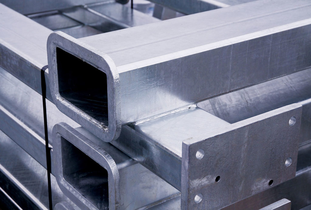
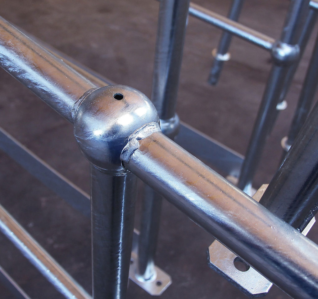
In open-ended SHS, RHS and pipe sections, a hanging hole is required at each end to allow wire to pass through. If the hollow section is capped, additional holes for venting are required. For SHS and RHS sections, holes should be placed in the corners. In pipe sections, holes are required to be as close to the outside diameter as possible. Holes placed in the centre of end caps will allow air pockets to form or zinc to pool. The minimum acceptable number of venting holes is one each end placed diagonally opposite. If there are no means of holding the item, two holes each end are required, with holes located diagonally opposite each other. The size of the venting holes is critical for processing hollow sections. Sufficient air must escape at the same rate zinc is entering the section. Holes should be no less than 25% of the cross-section of the hollow section. *The minimum hole size acceptable on any item is 10mm, however as holes this size can prove ineffective, we recommend holes sizes of 12mm or greater.
Internal holes SHS, RHS, CHS and pipe sections
Internal holes are not recommended due to inherent safety concerns. Where internal holes are used, sections should be interconnected using mitred joints or interconnecting holes. Internal holes should be as close as possible in size to the cross-section of the hollow section to eliminate air pockets and zinc pooling inside the fabrication. The ends of the hollow sections must remain open. Hunter Galvanizing requires signed documentation to guarantee holes have been correctly placed.
Holes for Venting Tanks and Hollow Vessels
Specific attention to venting and draining is required when repairing large hollow items such as tanks, pods or vessels for galvanizing. The design of tanks and closed vessels must allow for pre-treatment chemicals, air and zinc to enter, fill and flow out of the enclosed space. A large filling hole (minimum of 50mm diameter for each 0.5 cubic metres) is required at the low end when suspended for galvanizing. A vent hole of equal dimensions will be needed diagonally opposite the filling hole to allow air to escape.
Internal baffles in tanks must have their corners cropped before installation or with large drainage holes to permit free flow of the air and zinc within. Access ports, bosses and openings should be finished flush inside and should be positioned so that all processing fluids can be drained out during the galvanizing process. Whilst processing tanks, a large volume of zinc will pass through the vessel. As a safety precaution we require heavy duty lifting lugs attached to each item. We recommend discussing this requirement with Hunter Galvanizing staff before fabrication.
General guidelines:
- Venting holes are required to be diametrically opposite.
- Minimum acceptable hole size is 50mm in diameter. Subject to tank size additional holes may be required.
- Internal baffles should be cropped top and bottom.
- Lifting lugs will be required to facilitate handling.
Distortion
The percentage of items affected by distortion issues is relatively low given the volume hot-dip galvanized. A number of factors can compromise an item’s dimensional stability. By understanding the causes of distortion and adopting simple design principles, the effects can be minimised.
Inherent internal stress is present in every steel section. Stresses may be a result of the steel mill rolling, handling and transport methods, or incurred during subsequent manufacturing or cold-working processes such as cutting, welding and hole-punching.
At galvanizing temperatures of 450°C, steel sections can experience a reduction of up to 50% in their yield strength. Whilst normal strength is returned upon cooling, this effect, combined with release of internal stresses, can result in distortion in some items.
Distortion can also be the result of different thermal expansion and contraction rates occurring when thin items such as sheet, plate and mesh are used in conjunction with items of thicker sections. Thin sections or weaker areas within a fabrication may lose their shape as heat is transferred through the item. Thermal and contraction rates also differ during the process of double dipping, increasing the propensity of some sections to lose their shape or distort.
Non-symmetrical sections or fabrications with cleats or plates welded to one side may bow. This potential is prevalent in channels and large welded beams.
Guidelines to follow
- To allow even heat transfer, avoid using combinations of thick and thin materials in the same fabrication.
- Bend curved members to the largest possible radii.
- Venting and draining holes should be as large as possible to allow timely immersion and withdrawal from the galvanizing bath. (refer to hole chart by clicking here)
- Fabricated items that are stronger in one area may suffer distortion in the weaker plane. Brace items that are weaker over large areas. Bracing material should be the same thickness as the item.
- Where angles or channels are used to rim or frame a tank, apertures must be provided in the corners.
- Items with large areas of unsupported plate or sheet may suffer from liquid drag when being withdrawn from below the surface of the molten zinc. Coupled with reduced yield strength some loss of shape can occur.
Please note: as distortion is generally a result of poor design and outside of our control, Hunter Galvanizing cannot be held responsible for items not meeting the recommended criteria.
Double Dipping
Subject to the overall size and degree of difficulty, items with dimensions greater than our baths may be double dipped. The term double dipping has no bearing on coating thickness; it relates to dipping a large item into the galvanizing bath one end at a time. To achieve a hot-dip galvanized coating over the entire surface one end is pre-treated and dipped in the molten zinc; the item is withdrawn, and turned end to end. The second end or side is then cleaned in pre-treatment chemicals and dipped.
The potential for distortion increases because sections of the fabrication remain cool whilst others are heated. As one end is heated to galvanizing temperatures (450°C) it will expand, whilst the opposite end remains at ambient temperature. The section may bow when the second end is immersed in the molten zinc. Additional lifting points may be required to facilitate double-dip handling. Distortion potential of items in this category should be discussed with Hunter Galvanizing before delivery.
Plate, sheet and coil sections
The potential for distortion is increased when using large areas of unsupported plate. Items should be designed to incorporate the smallest area of unsupported plate as possible. Small sections of plate will hold their shape better than large sheets.
Hunter Galvanizing offers some general guidelines:
Subject to overall dimensions and weld stresses, thicker plate sections hold less risk of distortion. Large areas of plate 12mm thick and less have a high probability of distorting if unsupported.
- Floors for platforms and panels of perforated sheet should be galvanized separately then bolted to supporting structures.
- Floors in box trailers will not remain flat and will display some degree of buckling.
- Plate 6mm and less will ripple when hot-dip galvanized.
- Plate sections should be limited to our bath sizes to eliminate the requirement for double dipping.
- Plate able to be suspended diagonally and submerged in one dip will allow heat to transfer evenly throughout the section.
- Folded, ribbed or corrugated sheet sections are less prone to distortion and generally hold their shape.
- Long lengths of thin plate will require a number of holes to allow the plate to be supported along one edge.
- Equalize stresses by cutting all edges in the same manner. Cold cutting methods such as guillotine will induce less stress than heated methods.
- Welding will increase the stress in plate items. A stitch or staggered weld will induce less stress than a full continuous weld; however this may lead to “blowouts”.
All items incorporating large areas of plate should be discussed with Hunter Galvanizing staff before fabrication.
Channels
Parallel flange channels and tapered flange channels have a non-symmetrical profile, causing heat to transfer unevenly and increasing the risk of distortion.
Hunter Galvanizing offers some general guidelines:
- Subject to their length, channels have the tendency to camber or sweep when galvanized. Where possible these sections should not be double dipped without discussion with Hunter Galvanizing staff.
- Welding cleats on one side of a channel will encourage the channel to camber along its length at galvanizing temperatures.
- Lintels fabricated from channel and flat bar present dual issues. A combination of the cross-section, coupled with welding stresses, may increase the opportunity of camber or sweep. Staggered welding to minimise the additional stress is recommended, however pre-treatment chemicals may become trapped and result in blowouts or staining during galvanizing.
- All channel sections including those fabricated as lintels or with cleats, should have holes placed near each end to enable them to be suspended and dipped with their toes up. Longer lengths may require additional lifting points; please confirm with Hunter Galvanizing staff.
Welded beams
Large fabricated beams or columns, including certain sizes of the pre-welded product range pose some issues when hot dip galvanized.
Hunter Galvanizing offers some general guidelines:
- Sections where the web thickness is less than half that of the flange thickness are prone to distortion because the thinner web expands at a faster rate than the thicker flanges.
- Subject to the depth of the web, the top flange may cool more rapidly as it is withdrawn from the bath, increasing the stress over the rest of the section.
- Twisting may result in large welded beams and columns due to the combination of longitudinal, transverse and sheer stresses within the section, coupled with the loss of yield strength (up to 50%) at galvanizing temperatures.
- Designers incorporating these sections should select sizes with the thickest possible web to assist in minimising the twisting action.
- Symmetrical stiffening ribs may assist in the control of the expansion and contraction of the section.
- Double dipping of welded beams and columns should be avoided at all times.
Hollow sections
Pipe and tube hollow sections (circular hollow sections, square hollow sections, rectangular hollow sections) hold stresses induced in their rolling and manufacture. At galvanizing temperatures the relieving of these stresses coupled with the loss of yield strength may result in camber or sweep forming in longer lengths.
Hunter Galvanizing offers some general guidelines:
- Lengths of tubular sections should remain proportional to their diameter or cross-section and lifting lugs or holes should be provided at quarter points.
- Venting and draining holes should be as large as possible to allow timely immersion in the bath and adequate drainage of zinc to prevent the loss of shape.
- Bracing at the end of long pipes may be required to prevent zinc drag or loss of shape when items are lifted from the galvanizing bath.
Welding
Poor welding techniques affect the quality of a hot-dip galvanized coating. By understanding the hot-dip galvanizing process, most issues related to welding can be avoided. Internal stresses developed during welding can result in distortion during the galvanizing process. Items should be designed so they can withstand weld stress despite reduction and elasticity.
Guidelines to follow:
- Heat-induced stress can be minimised by staggering welds. Welding should be as symmetrical as possible and use opposing weld shrinkage forces to balance each other.
- Symmetrical sections such as square hollow section (SHS), rectangular hollow section (RHS), and pipe, should be used where possible. Avoid designs where plates and cleats are welded to one side.
- Where possible, use butt welds in preference to lap welds.
- Face joints of lap welds downwards to avoid collection of moisture and sediment.
- Where possible, restrict the size of the welding seam and apply in a symmetrical or even manner in a fabricated item.
